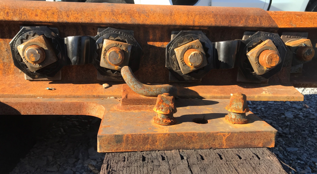
Testing Site 1 – Controlled Environment – TTCI – Colorado Test Site
Location & Testing Entity:
Transportation Technology Center, Inc. (TTCI),is a wholly owned subsidiary of the Association of American Railroads. Headquartered in Pueblo, Colorado, TTCI is a world-class transportation research and testing organization, providing emerging technology solutions for the railway industry throughout North America and the world. TTCI manages the Federal Railroad Administration’s (FRA) Transportation Technology Center (TTC), located just 21 miles northeast of Pueblo, Colorado. TTC is operated under a care, custody, and control contract with the FRA. This 52-square mile, secure and remote site operates with a vast array of specialized laboratories and track. TTC enables isolated testing for all categories of freight and passenger rolling stock, vehicle and track components, and safety devices. There are 48 miles of railroad track available for testing locomotives, vehicles, track components, and signaling devices at the Transportation Technology Center (TTC), Pueblo, Colorado. Specialized tracks are used to evaluate vehicle stability, safety, endurance, reliability, and ride comfort. Using TTC’s tracks eliminates the interferences, delays, and safety issues encountered on an operating rail system.
For more information on the Transportation Technology Center, Inc. (TTCI) please visit https://aar.com/
Testing Process and Parameters:
- Multiple live track locations were chosen. Installation to run from June 2018 to Dec 2018 for a total of six months.
- The existing joint bar assemblies had new bolts, washers and nuts installed on each side of the track.
- Once the Joint bar assemblies were installed as per standard proactive—Railinklock System™ units were installed over the nuts on each side of the track.
- Nut positions were marked with a white permanent marker and baseline photos were taken of each of the four installations—Zone 1 Inside, Zone 1 Outside, Zone 2 Inside and Zone 2 Outside.
- Monthly each installation was checked and photographed to establish whether or not there was any movement of the nuts.
- At the end of six months, the installations were checked for the last time and photographed.
- TTCI provided a final report indicating that the test was successful—the Railinklock System™ Units did not allow the nuts to move during the six-month period.
Testing Photographs:
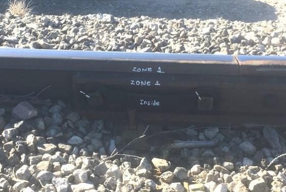
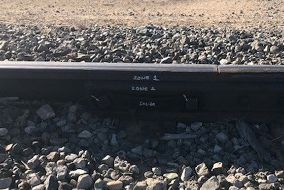
Zone 1 Inside – Six month Photo
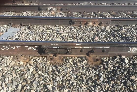
Zone 1 Outside – Baseline Photo
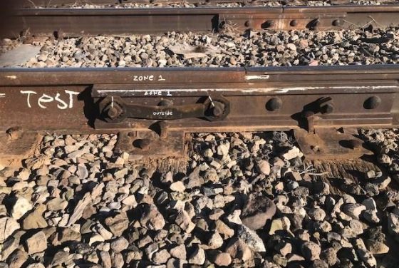
Zone 1 Outside – Six month Photo
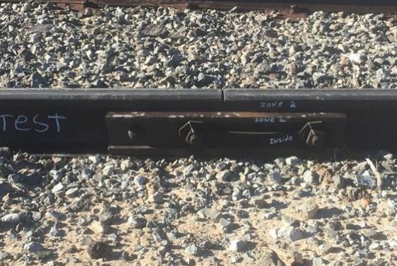
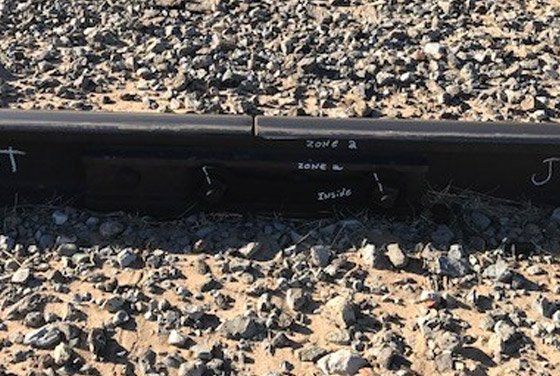
Zone 2 Inside – Six month Photo
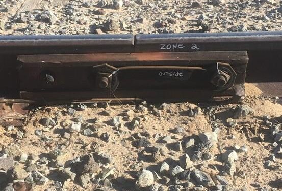
Zone 2 Outside – Baseline Photo
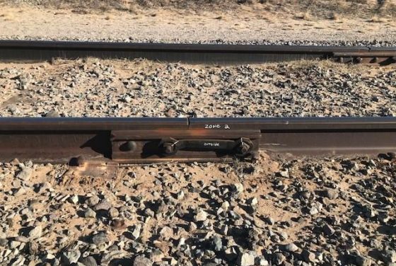
Section 2 Outside – Six-month Photo
For more information on the Transportation Technology Center, Inc. (TTCI) please visit https://aar.com/
Testing Site 2 – Live-Track, Third-Party Public Railway Corporation
Testing Entity:
Third-party public railway corporation – with a focus on safety, this company saw the potential for Railinklock System™ to further fortify the joints in railroad tracks by adding a second level of security on the joint and frog bar nuts. They believed that Railinklock System™ could potentially add a number of benefits:
- A second level of security to keep the nuts on the joint and frog bar units from loosening between maintenance checks including remote, difficult to reach or known problematic locations where the joint and frog bars have extra pressure and in heavy traffic locations such as rail yards, junctions and branches or spurs.
- Provide backup for human error—missing the tightening of a nut.
- Possibly saving maintenance by requiring fewer retorquing checks or allowing those checks to be completed in an automated way, some portion of the time via drone or camera.
With those possibilities in mind the Railinklock System test was initiated in August 2018 to run for a minimum of 6 months on a live track with normal route traffic.
Location:
The designated location was in Eastern USA, on an established railway route with standard rail tracks.
Testing Process and Parameters:
- Multiple live track locations were chosen.
- The tracks were cut and new joint bar assemblies were installed including new bars, bolts, washers and nuts on each side of the track.
- Once the Joint bar assemblies were installed as per standard procedure – Railinklock System™ units were installed over the nuts on each side of the track.
- Nut positions were marked with a white permanent marker and baseline photos were taken of each of the four installations—Section 1 Inside, Section 1 Outside, Section 2 Inside and Section 2 Outside.
- After six months had passed, each installation was checked and photographed.
- At the end of six months, the installations were checked to establish whether or not there was any movement of the nuts and photographed.
- The test was acknowledged to be a success as no movement of the nuts was detected on any of the four installations.
- The site was revisited at the end of eighteen months and again photographed – no movement of the nuts was detected on any of the installations.
Testing Photographs:
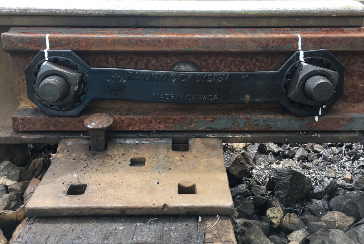
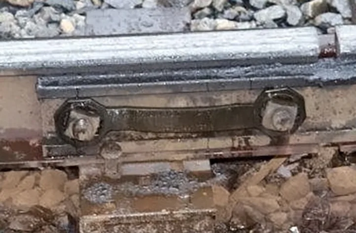
Section 1 Inside – Eighteen-month Photo
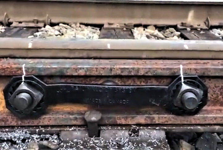
Section 1 Outside – Baseline Photo
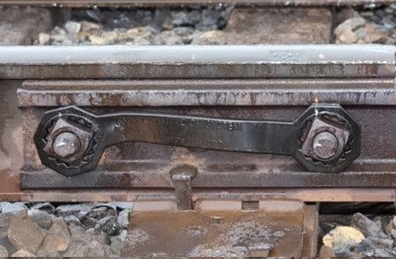
Section 1 Outside – Eighteen-month Photo
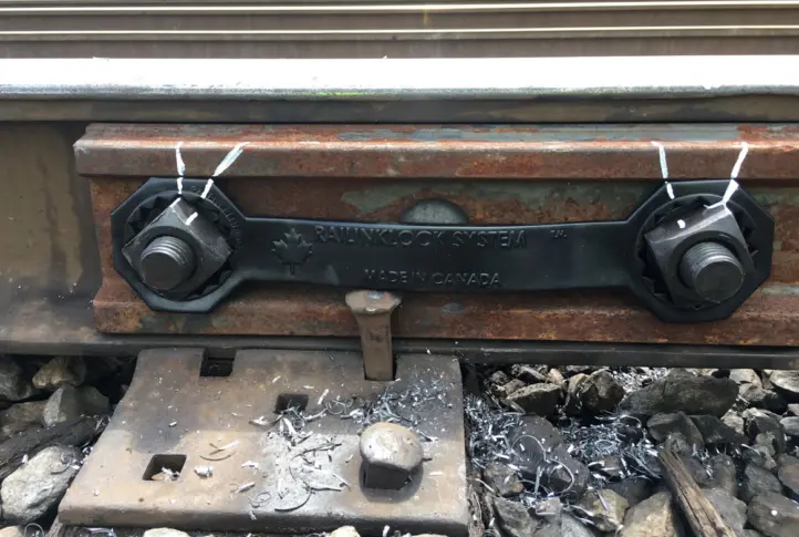
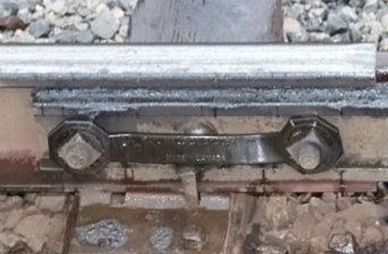
Section 2 Inside – Eighteen-month Photo
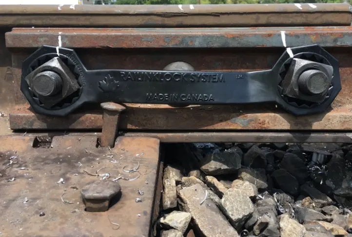
Section 2 Outside – Baseline Photo
Frog Bar Test Fit
During the installation of the Railinklock System™ second test it became apparent that the nuts and bolts on not only the Joint bars but also the Frog bars were susceptible to coming loose. The substantial vibration/movement of the track when a train is passing over it causes the nuts securing the bolts on both the Joint and Frog bars to slowly undo. This vibration/movement is the primary cause of the nuts loosening on the bolts, potentially causing the Joint and Frog bars to separate from the track.
The shorter thicker Railinklock System™ units were developed specifically to address the specialized nature of the Frog bars and the spacing and size of Frog bar bolts and nuts. While a vibration test was not carried out—it can be theorized that if the Railinklock System™ Joint bar units will function to stop any rotation of the nuts—the thicker, shorter Frog bar Railinklock System™ units will do the same.
